Module
Ports
Image
Sample code for
TI CE Graphing Calculator
White LED
*
OUT 1
OUT 2
OUT 3
Turn on the White LED module connected to OUT 1:
Send("CONNECT LED 1 TO OUT 1")
Send("SET LED 1 ON")
Servo Motor
OUT 3
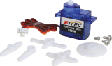
Rotate the shaft of the Servo Motor connected to OUT 3 counter clockwise by 90°:
Send("CONNECT SERVO 1 TO OUT 3")
Send("SET SERVO 1 TO -90")
Equivalent code using a variable with eval():
angdeg:=-90
Send("CONNECT SERVO 1 TO OUT 3")
Send("SET SERVO 1 TO eval(angdeg)")
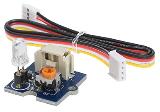
Analog Light Sensor
IN 1
IN 2
IN 3
Read and display ambient light level from the sensor connected to IN 2:
Send("CONNECT LIGHTLEVEL 1 TO IN2")
Send("READ LIGHTLEVEL 1")
Get(L):Disp(L)
Ultrasonic Ranger
IN 1
IN 2
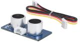
Read and display measured distance from the ranger connected to IN 2:
Send("CONNECT RANGER 1 TO IN2")
Send("READ RANGER 1")
Get(R):Disp(R)
Vibration Motor
OUT 1
OUT 2
OUT 3
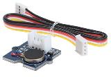
Turn on the Vibration Motor connected to OUT 1:
Send("CONNECT VIB.MOTOR 1 TO OUT 1")
Send("SET VIB.MOTOR 1 TO ON")
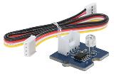
Temperature
Sensor
IN 1
IN 2
IN 3
Read and display the ambient temperature from the sensor connected to IN 3:
Send("CONNECT TEMPERATURE 3 TO IN3")
Send("READ TEMPERATURE 3")
Get(T):Disp(T)
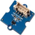
Temperature and
Humidity Sensor
IN 1
IN 2
IN 3
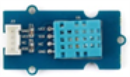
Connect the DHT sensor to port IN 2
Send( "CONNECT DHT 1 TO IN2 ")
Read the temperature from the DHT sensor connected to IN 2:
Send( "READ DHT 1 TEMPERATURE")
Get temperature
Read the humidity from the DHT sensor:
Send "READ DHT 1 HUMIDITY"
Get humidity
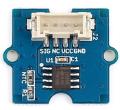
Hall Sensor
IN 1
IN 2
IN 3
Connect the Hall effect sensor to IN3 port:
Send "CONNECT ANALOG.IN 1 TO IN 3"
Read the value of the magnetic field reported by the sensor:
Send "READ ANALOG.IN 1"
Get m
Moisture Sensor
IN 1
IN 2
IN 3
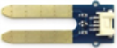
Connect moisture sensor to IN 1:
Send "CONNECT MOISTURE 1 IN 1"
Configure the measurement range to be between 0 and 100. The range is an index and has no units.
Send "RANGE MOISTURE 1 0 100"
Read the sensor:
Send "READ MOISTURE 1"
Get moisture
MOSFET
OUT 1
OUT 2
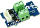
Connect the MOSFET to the OUT 1 port:
Send "CONNECT ANALOG.OUT 1 TO OUT 1"
Control the connected motor/pump at 50% speed for 3 seconds:
Send "SET ANALOG.OUT 1 128 TIME 3"
Water Pump
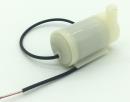
It is controlled through a MOSFET module.