| • | Do not expose the |
| • | Do not disassemble or mistreat the |
| • | Do not chain together multiple |
| • | Use only the USB cables provided with the |
| • | Use only the TI provided power supplies: |
| - | TI Wall Charger included with the TI‑Innovator™ Hub |
| - | Optional External Battery Pack |
| - | 4AA battery holder included in the TI‑Innovator™ Breadboard Pack |
| • | Ensure that the components receiving power from the |
| • | Avoid using the |
| • | Do not insert the leads of LEDs and other components directly into the |
| • | Do not connect the 5V receptacle pin on the |
| • | Connecting the top row of receptacle pins (BB1-10) to the bottom row (grounding and power pins) is not recommended. |
| • | No pin on the |
| • | Do not connect the positive and negative leads of a power source to the same group of 5 pins on the breadboard. Doing so could damage the breadboard and the power source. |
| • | Observe the correct polarity: |
| - | When connecting the breadboard to the |
| - | When connecting components that are sensitive to polarity, such as LEDS and the TTL Power MOSFET. |
| • | Use the correct Input or Output port as required for each module. |
| - | Vibration Motor – supported on OUT 1, OUT 2, and OUT 3. |
| - | Servo Motor – use OUT 3 only. |
| - | White LED – supported on OUT 1, OUT 2, and OUT 3. |
| - | Analog Light Sensor – supported on IN 1, In 2, and IN 3. |
| - | Ultrasonic Ranger – supported on IN 1, IN 2. |
| • | Use an Auxiliary Power Source for modules that require more than 50 mA, including: |
| - | Vibration Motor |
| - | Servo Motor |
| • | Do not hold the Servo Motor’s shaft while it is rotating. Also, do not rotate the Servo Motor by hand. |
| • | White LED: |
| - | Do not bend the leads repeatedly; this will weaken the wires and may cause them to break. |
| - | The LED requires the correct polarity when inserted into its socket. For details, refer to the instructions for assembling the LED in the TI‑Innovator™ Technology eGuide (here). |
| - | The LED requires the correct polarity when inserted into its socket. For details, refer to the instructions for assembling the LED (here). |
| • | No I/O module can sink or source greater than 4 mA. |
| • | Do not expose the |
| • | Do not disassemble or mistreat the |
| • | Do not put anything heavier than 1 Kg or 2.2 lbs on the |
| • | Use only the USB cables provided with the |
| • | Use only the Ribbon cables provided with the |
| • | Use only the TI provided wall charger included with the |
| • | The front-mounted |
| • | For best results, leave the Slide Case off of your graphing calculator. |
| • | For best performance, use |
| • | For best performance, use |
| • | Do not turn the Holder pegs on the Calculator Platform without lifting them first. They could break. |
| • | Do not use the marker as a lever to pull or push the |
| • | Do not unscrew the case enclosure on the bottom of the |
| • | Do not move Rover after executing a program. The internal gyroscope may unintentionally try to get the Rover back on track using the initial location. |
| • | When inserting the Breadboard Ribbon Cable into the |
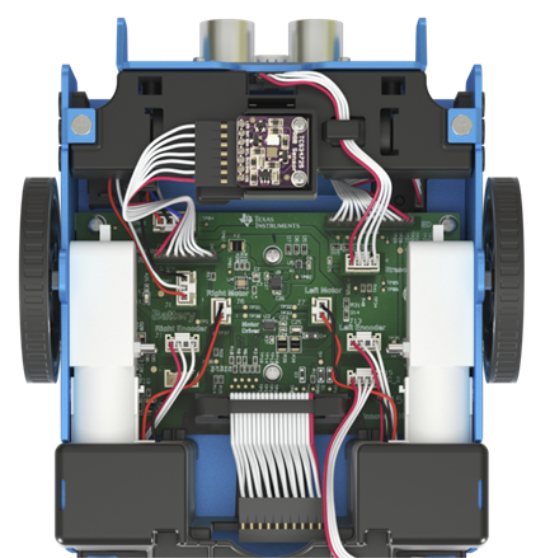
Caution: If you dislodge or disconnect any of the cables, use this image as a reference for correct hookups.Reference to Bottom View