TI‑Innovator™ Breadboard Pack
The breadboard and its components (purchased separately) let you build breadboard projects and connect them to the TI‑Innovator™ Hub through its Breadboard Connector pins.
The breadboard components include:
|
•
|
A breadboard and jumper cables for creating electrical connections. |
|
•
|
Addressable components, such as LEDs and sensors, that respond to Hub commands. These are listed in the table below. |
|
•
|
Passive components, such as resistors, capacitors, and manual switches that are not directly addressable by the Hub but are required in many breadboard projects. |
|
•
|
A Battery Holder that holds four AA batteries. Batteries are not included. |
Addressable Components
|
Component
|
Image
|
|
Used with pins
|
Description
|
|
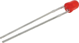
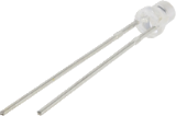
Red LEDs
|
|
|
BB 1-10
|
Light-emitting diode that emits light when current passes
through it.
|
|
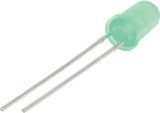
Green LEDs
|
|
|
BB 1-10
|
Light-emitting diode that emits light when current passes
through it.
|
|
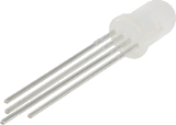
RGB (Red-Green-Blue) LEDs
|
|
|
BB 8-10
|
Light-emitting diode with independently adjustable red, green and blue elements. Can produce a
wide variety of colors.
|
|
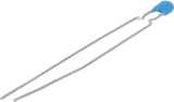
Thermistor
|
|
|
BB 5,6,7 (analog input required)
|
Resistor whose resistance changes based on temperature. Used for measurement and control.
|
|
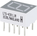
7-segment Display
|
|
|
BB 1-10
|
Array of LEDs arranged to display numbers and some
alphabetic characters. Also has an LED for a decimal point.
|
|
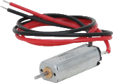
Small DC Motor
|
|
|
BB 1-10 (uses digital to generate software PWM)
|
Motor that converts direct current electrical power into mechanical power.
|
|
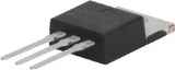
TTL Power MOSFET
|
|
|
BB 1-10
|
Transistor used for amplifying or switching
electronic signals.
|
|
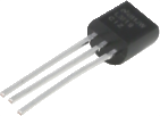
TI Analog Temperature Sensor
|
|
|
BB 5,6,7 (analog input required)
|
Sensor that reports a voltage proportional to the ambient temperature within a range of −55°C to 130°C.
|
|
Visible Light Sensor
|
|
|
BB 5,6,7 (analog input required)
|
Sensor that reports the level of ambient light.
|
|
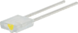
Infrared Transmitter LTE‑302,
yellow dot
|
|
|
BB 1-10 (digital output)
|
Side emitting Infrared LED, designed to be paired with the
LTR-301 Photo-Transistor.
|
|
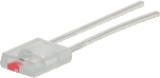
Infrared Receiver LTR‑301,
red dot
|
|
|
BB 1-10 (digital input)
|
Side sensing Infrared photo transistor, designed to be paired
with the LTE-302 Infrared Emitter.
|
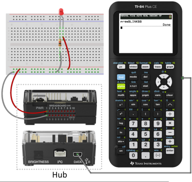
Sample Code to Blink a Breadboard LED
The following TI CE graphing calculator(s) program uses Send and Wait commands to blink a specific LED on the breadboard.
Note: This program operates correctly only if the calculator is connected to the Hub and the LED is physically connected to (breadboard pin 1) on the Hub.
PRGM: BLINKBB
Send("CONNECT LED 1 TO BB1")
For(N,1,10)
Send("SET LED 1 ON")
Wait 1
Send("SET LED 1 OFF")
Wait 1
End
Send("DISCONNECT LED 1")
Note: If you are using TI‑Nspire™ CX technology, omit the parentheses, and change End to EndFor.
|
|
The Hub command string "CONNECT LED 1 TO BB1" tells the Hub that an LED on the breadboard is connected to pin on the Hub. After sending this command, your code can address the LED as "LED 1." The CONNECT command is required only for I/O Modules and breadboard components. It does not apply to on‑board components such as the built-in speaker.
See also: TI-Innovator™ Hub Ports and Breadboard Usable Pins
See also: Breadboard Components and Usable Pins
Breadboard Basics
The breadboard makes it easy to connect the electronic components of a project by inserting component leads and jumper cables into pins on the breadboard.
The pins are arranged in groups of 5. The 5 pins in each group are electrically connected to each other at the back of the board. You connect leads and cables together by inserting them into pins within the same group.
|
•
|
Power rails at the top and bottom are marked with red (+) and blue (–) stripes. The groups in each rail are electrically connected along the entire length of the stripe. |
|
•
|
The remaining 5-pin groups on the board are labeled with numbers and letters. Each group is electrically isolated from the others. |
|
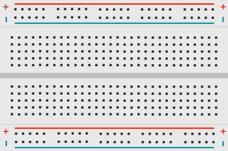
Front of board showing power rails and connection pins
|
|
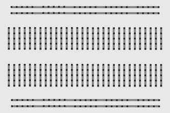
Interconnections at back of board (normally hidden). The 5-pin groups in each power rail are interconnected. All other 5-pin groups are isolated.
|
The gap at the center of the breadboard allows easy connection of electronic components provided as dual-inline packages.
You use jumper cables between the Hub and the breadboard to power breadboard components and to control or monitor them through program code. The Hub has 20 labeled pins, including 10 signal pins, 8 ground pins, one 3.3V power pin, and one 5.0V power pin.
Learn More
For a list of precautions to take while using the breadboard and its components, refer to General Precautions (here).
