Exploring with Geometric Construction Tools
You can investigate scenarios by adding objects from the Construction tools. The constructions are dynamic. The midpoint of a line segment, for example, is updated automatically when you manipulate the endpoints.
While a construction is in progress, a tool appears in the work area (for example, Parallel  ). To cancel, press ESC.
This tool lets you bisect a segment or define a midpoint between any two points. The points can be on a single object, on separate objects, or on the work area.
| 1. | From the Construction menu, select Midpoint. (In the Graphs application, click Geometry > Construction > Midpoint.) |
| 2. | Click a point or location to define the first point. |
| 3. | Click a second point or location to complete the midpoint. |
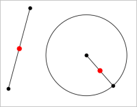
This tool creates a parallel line with respect to any existing line. The existing line can be a Graphs axis or any side of a triangle, square, rectangle, or polygon.
| 1. | From the Construction menu, select Parallel. (In the Graphs application, click Geometry > Construction > Parallel.) |
| 2. | Click the object that will serve as the reference line. |
| 3. | Click a location to create the parallel line. |
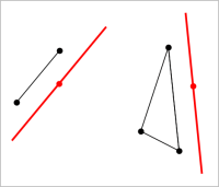
You can drag the parallel line to move it. If you manipulate the reference object, the line remains parallel.
You can create a line that is perpendicular to a reference line. The reference can be an axis, an existing line, a segment, or one side of a triangle, rectangle, or polygon.
| 1. | From the Construction menu, select Perpendicular. (In the Graphs application, click Geometry > Construction > Perpendicular.) |
| 2. | Click a location or existing point through which the perpendicular line should pass. |
| 3. | Click the item that will serve as the reference line. |
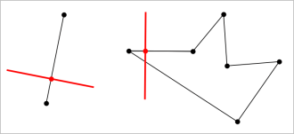
You can drag the intersection point to move the perpendicular. If you manipulate the reference object, the line remains perpendicular.
You can create a perpendicular bisector on a segment, on one side of a triangle, rectangle, or polygon, or between any two points.
| 1. | From the Construction menu, select Perpendicular Bisector. (In the Graphs application, click Geometry > Construction > Perpendicular Bisector.) |
| 2. | Click the item that will serve as the reference line. —or— Click two points to create a perpendicular bisector between them. |
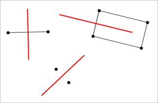
This tool creates an angle bisector. The points of the angle can be on existing objects, or they can be locations on the work area.
| 1. | From the Construction menu, select Angle Bisector. (In the Graphs application, click Geometry > Construction > Angle Bisector.) |
| 2. | Click three locations or points to define the angle. The second click defines the vertex of the angle. |
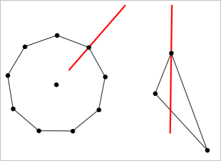
The angle bisector adjusts automatically as you manipulate its defining points.
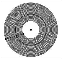
The Locus tool enables you to explore the range of motion of one object with respect to another object as constrained by a shared point.
| 1. | Create a segment, line, or circle. |
| 2. | Create a point on the segment, line, or circle. |
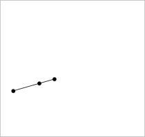
| 3. | Create another object that uses the point created in the previous step. |
|
|
| 4. | From the Construction menu, select Locus. (In the Graphs application, click Geometry > Construction > Locus.) |
| 5. | Click the point shared by the objects. |
| 6. | Click the object defined to share the point (this is the object to vary). |
The continuous locus is displayed.
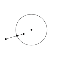
This tool operates similarly to a geometric compass used for drawing circles on paper.
| 1. | From the Construction menu, select Compass. (In the Graphs application, click Geometry > Construction > Compass.) |
| 2. | To set the width (radius) of the compass: |
Click a segment.
—or—
Click any side of a triangle, rectangle, polygon, or regular polygon.
—or—
Click any two existing points or locations on the work area.
| 3. | Click a location to establish the centre of the circle and complete the construction. |
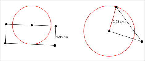
The radius adjusts automatically as you manipulate the original segment, side, or points used to define the radius.
 Creating a Midpoint