B" port at the bottom of the
 This section describes some problems you may encounter and gives suggestions on how to resolve the problem.
If you need more assistance, contact TI-Cares.
TI-Innovator™ Hub Troubleshooting
On-Board Hub Components Troubleshooting
TI-Innovator™ Rover Troubleshooting
Programming with TI-Basic Troubleshooting
| - | Make sure that the calculator is turned on. |
| - | If you are using a USB Unit-to-Unit (Mini-A to Mini-B) cable to connect to a calculator, make sure to connect the "B" end of the cable to the "DATA B" port at the bottom of the |
| - | Make sure your calculator has the latest operating system. |
| - | Make sure the end of the USB cable connected to the calculator is inserted completely. |
| - | Unplug the USB cable from the TI-Innovator™ |
| - | Make sure you are using the latest version of TI-Nspire™ CX software. The latest version installs a driver that allows the computer to recognize the TI-Innovator™ |
| - | Make sure you are connecting to the TI-Innovator™ Hub using the "DATA B" port on the TI-Innovator™ port |
| - | Unplug the USB cable from the TI-Innovator™ |
| - | If you are not using the USB cable provided with the TI-Innovator™ |
| - | Turn off the host calculator or computer. |
– OR –
| - | Disconnect the USB cable. |
If the error LED blinks and the speaker makes a tone, there is an error in the commands being sent to the TI-Innovator™
The TI-Innovator™

![]()
| - | Download the test program and run this to test your on-board component. |
| - | Make sure your program is using values that align with the ranges that the on-board components support |
| - | RGB: Range from 0 to 255 for level of intensity |
| - | Speaker: Range from 40 to 4000 Hz |
The on-board COLOR/RGB commands and SOUND/SPEAKER commands can not be used at the same time. User programs should wait until the SOUND/SPEAKER command to complete before sending COLOR/RGB command to TI-Innovator™
LED light sources flicker at high speeds. While the human eye can not detect this flickering, the light brightness sensor does register this flicker and reports the values it is reading.
![]()
| - | Check to make sure it is charged |
| - | Make sure it is turned on. |
| - | Make sure all cables are attached. |
| - | Make sure breadboard cable is in correct configuration (red wire on correct side) |
| - | Make sure all the breadboard pins are straight. |
| - | Make sure you have latest sketch |
| - | Make sure you have latest OS |
| - | Try test program |
| - | Do not have anything besides calculator on top of Rover. |
| - | If using the pen holder, make sure that the pen is not inserted so far it is lifting up the Rover. |
| - | Clean casters |
| - | Use on smooth, flat surface for best results |
| - | Check to see if orientation matches the expectations of your program. |
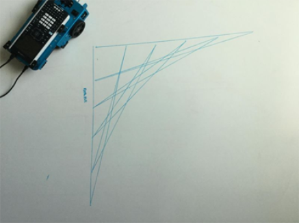
| - | Rover is not a precision drawing tool. You should expect a level of imprecision with specific shapes. |
| - | When turning, Rover can have a +/- 0.5 degree variation. The greater number of segments (or turns) the more that variation can compound. |
| - | Best surfaces to use Rover is a flat smooth surface (not carpet or tile) |
There are two methods to draw shapes (or functions) with Rover.
They have different levels of precision and may result in different results even for the same general shape (e.g. octagon).
Method 1: Using FORWARD/BACKWARD/LEFT/RIGHT – these commands move Rover by the specified distance and angle. The angular movement may not be precise and depends on the surface as well as the presence of the marker.
Method 2: Using ‘TO XY’, ‘TO POLAR’ – these commands move Rover to specific coordinates with more precise turns. Even with these commands, small errors add up after multiple segments. Functions and shapes that use a large grid size and/or more than 18 segments may result in a drawing that does not match the expected shape.
There are two different commands related to Rover turning
| - | RV LEFT/RV RIGHT commands: These commands will tell Rover to turn the specified angle relative to Rover’s current position. |
| - | RV TO ANGLE – This command will move to the specific angle on the unit circle |
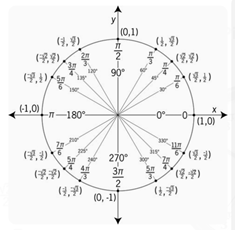
RV LEFT 30
RV LEFT 45
Will result in Rover at an angle of 75 degrees
RV TO ANGLE 30
RV TO ANGLE 45
Will result in Rover at an angle of 45 degrees
Make sure your program is using the turn command that matches your expectations of Rover’s movement.
These commands use degrees as the default unit even if the calculator setting is in radians.
You can specify RADIANS or GRADS (gradians) for Rover turns in the command through the “Hub -> Rover (RV) -> RV Settings” menu
Rover uses a default unit of 10 cm (~4 in).
So the command - RV FORWARD 1 – will cause Rover to move forward by 10 cm
It is equivalent to the “RV FORWARD 1 UNITS” and “RV FORWARD 0.1 M” commands
To move Rover for specific distances, you can use the ‘M’ setting to specify meters.
The marker holder supports common thin markers or dry erase markers. The marker holder is designed to let gravity do the work to hold the marker in place. The tip of the marker will stay in the proper location, even if there is some movement at the other end of the marker.
The default position of Rover is on the origin of a Cartesian grid point down the positive x-axis.
Original orientation is: position (0,0); heading 0 degrees (east – pointing toward the positive x-axis).
TO XY turns to the proper angle first, then moves straight to the point.
TO XY 1 1 turn 45 degrees to the left and then move sqrt(2) units (@ 10cm/unit = 14.14cm).
See also Rover>Setup>SET RV.POSITION
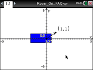
Table 1: Example 1:
|
|
|
The Rover commands fall into two categories:
| 1. | Queued execution: All of the Rover motion commands – FORWARD, BACKWARD, LEFT, RIGHT, ANGLE – are queued on the TI-Innovator Hub. They may execute at a future time. |
| 2. | Immediate execution: Other commands – like the ones to read the sensors or set the RGB LED on the Rover – are executed immediately. |
This means that certain statements in your program will execute before statements that appear earlier in the program especially if the latter commands are part of the queued family.
For example, in the program below, the RGB LED will turn RED before the Rover stops moving:
Send "SET RV.COLOR 255 0 255" – immediately executed
Send "RV FORWARD 5" – queued command
Send "RV LEFT 45" – queued command
Send "RV RIGHT 90" – queued command
Send "SET RV.COLOR 255 0 0" – immediately executed
This can happen if the commands are queued for later execution. The calculator says ‘Done’ because the programs is done sending all the commands to the TI-Innovator Hub. The Hub will execute the commands to control the Rover even though the calculator program is complete.
While typically the battery charging status is shown immediately, it can take a minute for the battery status to show.
Charge the Rover for a couple of a couple minutes and wait for the battery status to display.
To completely disable the Rover, please turn the power switch to OFF and disconnect the USB cable from the graphing calculator.
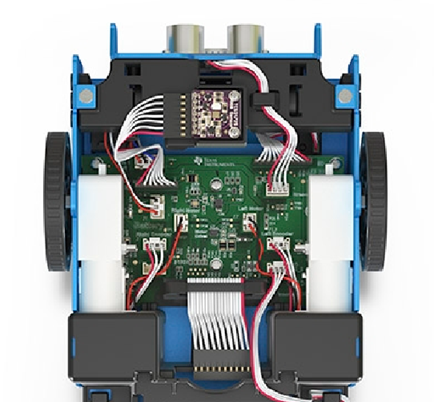
This can happen if the two motors do not have similar internal calibration. We are aware of this issue and are working on a solution via an update to the Hub sketch.
Make sure you are using the correct orientation of the tabs. The tabs have ‘CE’ and ‘CX’ engravings to fit the TI84Plus CE family and the TI-Nspire CX family of calculators respectively.
Reference the test programs.
Looking for loose connections.
Please refer to the wiring diagram below for reference.
| - | Check the caster for debris |
| - | Use compressed air to clean out. |
| - | The tires may have come off. Check to make sure they are completely seated on the wheel. |
| - | Smooth flat surface is recommended. |
| - | How to check to make sure they are fully seated on the wheel. |
Please re-align the pins in the original configuration before attaching to the Hub.
These commands will be implemented in a future release of the Hub sketch.
| - | Demo: Programs to do stuff. Take it for a test drive. |
| - | Test Programs: try one component at a time. Make sure they work. |
![]()
The following troubleshooting steps will help determine if there is something wrong with the white LED I/O module.
| - | Ensure that the LED is properly inserted in the socket. |
| - | Insert LED into socket - longer leg (lead) is positive (anode). If both leads are of equal length, the lead adjacent to the flat edge on LED casing is the negative (cathode) lead. |
| - | Download the test program and run this to test your white LED module component. |
| - | Ensure that you have connected the I/O module into correct port required by the program |
The following troubleshooting steps will help determine if there is something wrong with the analog light sensor I/O module.
| - | Download the test program and run this to test your analog light sensor I/O module component. |
| - | Ensure that you have connected the I/O module into correct port required by the program |
The following troubleshooting steps will help determine if there is something wrong with the vibration motor I/O module.
| - | Download the test program and run this to test your vibration motor I/O module component. |
| - | Ensure that you have connected the I/O module into correct port required by the program. |
The following troubleshooting steps will help determine if there is something wrong with the servo motor I/O module.
| - | Download the test program and run this to test your servo motor I/O module component. |
| - | Ensure that you have connected the I/O module into OUT3 and that the program you are using is calling OUT3. |
| - | The servo motor requires the TI-Innovator™ Hub to have external power. The PWR connector on the Hub lets you connect an auxiliary power source. You can use the TI Wall Charger or the External Battery. External power is required if the TI-Innovator™ |
| - | Overtime the servo motor may need to be recalibrated. Steps to recalibrate: |
| - | Connect External Power to TI- Innovator |
| - | Connect Servo Motor to OUT3 |
| - | Send the Command "CONNECT SERVO 1 TO OUT3" |
| - | Send the Command "SET SERVO 1 CW 0 TIME 100" (Sets speed to zero, time value can be increased if needed) |
| - | If the Servo does not move, then it’s already calibrated, If the servo is moving, use a screwdriver to move the potentiometer in the back of the motor until it stops. |
The following troubleshooting steps will help determine if there is something wrong with the ultrasonic ranger I/O module.
| - | Download the test program and run this to test your ultrasonic ranger I/O module component. |
| - | Ensure that you have connected the I/O module into correct port required by the program. |
The position of the sensor built-in to the TI-Innovator™
![]()
| • | TI-SensorLink is not a data collection solution. USB connected probes or Lab Cradle remains a superior solution for pure data collection and analysis. |
| • | The Hub commands for the TI-SensorLink with the Vernier analog sensors are currently not part of the Hub App (CE family) or the Hub menu (TI-Nspire™ CX). |
| • | The new commands and keywords will either need to be typed in OR copied from an existing program. Please note that any typographical errors in the keywords will result in an error indication in the sketch. |
![]()
| - | If you have pasted code from an external source or text editor, it might contain "curly" quotation marks (“...”) in places that require straight quotes ("..."). You may need to replace some or all of the curly quotes. |
| - | The syntax rules are slightly different between the TI CE Graphing Calculator and TI-Nspire™ CX technology. Code originally created for one platform may need to be modified to work on the other. |
| - | On the TI CE Graphing Calculator, make sure you don't have a space character at the end of a line of code. To find these trailing spaces in a line, move the cursor to the line and press the [2nd] and then right arrow key. Adjacent spaces in code can also cause a syntax error. |
| - | TI CE Graphing Calculator: Press the ON key. |
| - | TI-Nspire™ CX Handheld: Hold down the Home/ON key and press ENTER repeatedly. |
| - | Windows®: Hold down the F12 key and press Enter repeatedly. |
| - | Mac®: Hold down the F5 key and press Enter repeatedly. |
Make sure you are using the latest version of TI-SmartView CE software, version 5.2. This version installs the ‘
The TI-Innovator™
The error LED will blink if there is an error in the command structure and the sketch is unable to process the commands. Review the sample commands for the on-board, I/O modules, and breadboard components for ideas on how to modify your program.
![]()
| - | For sketch updating, make sure you are using the USB Standard A to Micro cable, not the USB Standard A to Mini-B cable. Connect the micro end of the cable to the PWR connector at the top of the Hub. |
| - | This could be a cable issue. Some USB cables are only for power, not for data. |
| - | Make sure you use the cable that comes with the TI-Innovator™ |
Yes.
![]()
| - | Press the On/Off button to ensure the battery is on. The external battery will turn itself off in 3 minutes if it is not connected to the TI-Innovator™ |
| - | Insure that the external battery has a charge. Press the On/Off button. If the LED lights do not light up the external battery needs to be charged. |
![]()